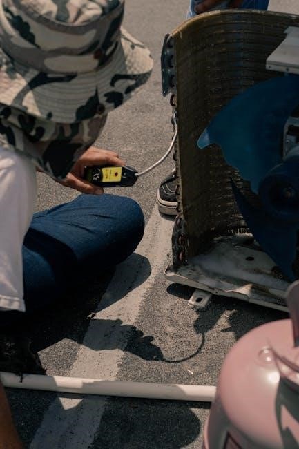
Understanding 3-phase air compressor pressure switch wiring diagrams is crucial for professionals․ These diagrams provide a roadmap to successful operation, ensuring safety and efficiency in industrial applications․
1․1 Overview of 3-Phase Systems
A 3-phase system operates using three alternating currents, each offset by 120 degrees․ This configuration enhances efficiency and power distribution, making it ideal for industrial applications․ The system consists of three live wires and a neutral wire, ensuring balanced loads and reduced voltage drop․ Its advantages include higher power output and better energy utilization compared to single-phase systems․
1․2 Importance of Pressure Switches in Air Compressors
Pressure switches are vital for regulating air compressor systems, ensuring they operate within safe pressure limits․ They monitor and control the compression cycle, preventing over-pressurization and potential damage․ By automating shutdown and startup, these switches enhance safety, reduce wear and tear, and optimize energy consumption, making them indispensable for efficient and reliable compressor performance․
1․3 Purpose of Wiring Diagrams for 3-Phase Air Compressors
Wiring diagrams for 3-phase air compressors serve as essential guides for professionals, illustrating the proper connections and components․ They ensure safe and efficient installation, maintenance, and troubleshooting․ By detailing electrical circuits and pressure switch integration, these diagrams prevent errors and guarantee compliance with safety standards․ Clear visuals and labels help technicians understand the system’s layout, facilitating accurate setup and future maintenance․

Understanding the Components of a 3-Phase Pressure Switch
A 3-phase pressure switch includes electrical contacts, a pressure sensor, and an enclosure․ These components work together to control motor operation, monitor pressure levels, and ensure safe functioning․
2․1 Key Components of a Pressure Switch
A 3-phase pressure switch consists of electrical contacts, a diaphragm or piston, a spring, and an enclosure․ The diaphragm detects pressure changes, while the spring provides the setpoint․ Electrical contacts control the circuit, and the enclosure protects internal components․ Together, these parts regulate the compressor motor based on pressure levels, ensuring efficient and safe operation․ Proper installation is essential for reliability․
2․2 How the Pressure Switch Operates in a 3-Phase System
In a 3-phase system, the pressure switch monitors air pressure and controls the compressor motor․ It detects pressure changes, triggering the contacts to open or close․ This regulates the motor’s operation, starting or stopping it based on set pressure levels․ The switch ensures efficient pressure maintenance, preventing over-pressurization and maintaining system safety․ Its operation is synchronized with the 3-phase power supply for reliable performance․
2․3 Types of Pressure Switches for Air Compressors
Pressure switches for air compressors are available in various types, including mechanical, digital, and pneumatic models․ Mechanical switches are the most common, offering reliable performance․ Digital switches provide precise pressure control and advanced features like adjustable setpoints․ Pneumatic switches are ideal for systems requiring non-electrical operation․ Each type is designed to meet specific application needs, ensuring efficient and safe compressor operation in diverse industrial settings․
Safety Precautions for Wiring a 3-Phase Air Compressor
Ensure proper grounding, disconnect power before work, and verify voltage compatibility․ Use appropriate PPE and follow manufacturer guidelines to prevent electrical hazards and ensure safe wiring practices․
3․1 Essential Safety Measures Before Starting
Before starting, ensure the compressor is disconnected from the power supply; Verify that all components are de-energized using a multimeter․ Wear appropriate PPE, including insulated gloves and safety goggles․ Familiarize yourself with the wiring diagram and manufacturer’s instructions․ Ensure proper ventilation in the work area to prevent inhalation of dust or fumes․ Double-check that all tools are calibrated and within safe operating conditions․ Never bypass safety features or skip precautions, as this can lead to severe electrical shock or equipment damage․ Always follow local electrical codes and standards to maintain a safe working environment․
3․2 Understanding Voltage and Current Requirements
Understanding voltage and current requirements is crucial for safe and efficient wiring․ Three-phase air compressors typically operate at 208V, 240V, 380V, 400V, or 480V․ Current requirements depend on the compressor’s horsepower and pressure switch specifications․ Always consult the manufacturer’s manual to ensure the wiring matches the system’s voltage and current ratings․ Proper conductor sizing and circuit breaker selection are essential to prevent overheating and ensure reliable operation․
3․3 Importance of Proper Grounding
Proper grounding is essential for safety and reliable operation of 3-phase air compressors․ It protects against voltage spikes, ensures safe operation, and prevents equipment damage․ A well-grounded system reduces the risk of electrical shocks and ensures the pressure switch functions correctly․ Always follow manufacturer guidelines and local electrical codes to establish a secure grounding connection, safeguarding both the compressor and operator from potential hazards․
Reading and Interpreting the Wiring Diagram
Reading and interpreting wiring diagrams is essential for understanding connections and ensuring proper installation․ It involves identifying symbols, phases, and color codes to guarantee safe and functional setups․
4․1 Understanding the Symbols and Notations
Wiring diagrams use specific symbols and notations to represent components like pressure switches, motors, and connections․ Understanding these symbols is crucial for identifying parts and their relationships․ Color coding indicates phase wires (e․g․, red, yellow, blue for live phases) and neutral or ground wires․ Proper interpretation ensures accurate installation and troubleshooting, avoiding potential electrical hazards․ Familiarizing with these conventions is essential for safe and efficient setup․
4․2 How to Identify Phases and Neutral Wires
In a 3-phase system, identifying phases and neutral wires is crucial for safety and proper functionality․
Typically, phase wires are color-coded red, yellow, and blue, while neutral wires are black or gray․
Ground wires are usually green or green with a yellow stripe․
Always refer to local electrical codes or wiring diagrams for specific applications, as color codes may vary by region․
4․3 Role of Color Coding in Wiring Diagrams
Color coding is essential in wiring diagrams for quick identification of wire functions․
Typically, phase wires are red, yellow, and blue, while neutral wires are black or gray․
Ground wires are often green or green with a yellow stripe․
This standardized system helps reduce errors and enhances safety during installation and troubleshooting;

Step-by-Step Installation and Wiring Guide
Follow detailed steps to install and wire the pressure switch, ensuring proper connections for efficient and safe operation of your 3-phase air compressor system․
5․1 Preparing the Components and Tools
Gather all necessary components, including the pressure switch, wiring harness, and connectors․ Ensure you have tools like wire strippers, screwdrivers, and multimeter for accurate connections․ Verify compatibility and ratings of each part with your 3-phase system to avoid mismatches․ Organize the workspace for efficient installation, referencing the wiring diagram for clarity and precision․
5․2 Connecting the Pressure Switch to the Compressor
Refer to the wiring diagram to identify terminals for power, control, and sensor connections․ Match the compressor’s electrical terminals with the pressure switch, ensuring secure and proper wire connections․ Use appropriate connectors and tighten screws firmly․ Double-check all wires for correct polarity and phase alignment․ Ensure the pressure switch is mounted securely and aligned with the compressor’s electrical panel for safe and efficient operation․
5․3 Testing the Wiring for Proper Functionality
After completing the connections, use a multimeter to verify the wiring integrity․ Check for short circuits or open circuits between terminals․ Ensure the voltage matches the compressor’s specifications when powered on․ Test the phase sequence to confirm proper rotation․ Activate the pressure switch and monitor the compressor’s operation to ensure smooth startups and shutdowns․ Verify all safety features and controls function as intended․

Troubleshooting Common Issues
Identify and diagnose wiring and switch malfunctions promptly to ensure safe operation․ Common issues include loose connections, faulty pressure switches, and incorrect phase wiring․ Always refer to the wiring diagram for guidance․ Check for blown fuses or tripped breakers and ensure proper grounding․ Test the pressure switch’s functionality and verify the compressor’s power supply․ Addressing these issues quickly prevents further damage․
6․1 Identifying and Diagnosing Wiring Problems
Start by turning off the power supply and verifying all safety precautions․ Check for loose connections, damaged wires, or incorrect phase wiring․ Use a multimeter to test voltage and continuity․ Look for blown fuses or tripped breakers․ Ensure proper grounding to prevent electrical hazards․ Refer to the wiring diagram to trace and identify faulty circuits․ Addressing these issues promptly ensures reliable operation and prevents further damage to the system․
6․2 Common Issues with Pressure Switches
Common issues with pressure switches include faulty contacts, incorrect pressure settings, or dirt accumulation․ These problems can cause the compressor to malfunction, leading to intermittent operation or complete shutdown․ Regular cleaning and inspection are essential to maintain functionality․ Ensuring proper installation and adjustment of the switch prevents premature wear and potential safety hazards․ Addressing these issues promptly helps maintain efficient and reliable compressor performance․
6․3 How to Fix Wiring-Related Malfunctions
To fix wiring-related malfunctions, start by checking all connections for looseness or damage․ Verify that the voltage matches the compressor’s requirements and ensure proper grounding․ Use a multimeter to test for short circuits or open lines․ Consult the wiring diagram to confirm connections are correct․ Replace any damaged wires or components, and ensure all terminals are securely tightened․ Regular maintenance can prevent such issues from recurring․

Maintenance and Upkeep of the Wiring System
Regularly inspect wiring for wear, clean connections, and replace damaged components․ Ensure all terminals are tight and protected from environmental factors to maintain efficiency and safety․
7․1 Regular Checks for Wear and Tear
Perform routine inspections of wires and connections to identify frays, cracks, or corrosion․ Use the wiring diagram to locate critical points and ensure all components are securely fastened․ Replace any worn-out parts immediately to prevent malfunctions․ Regular checks help maintain reliability and safety in the 3-phase air compressor system, ensuring optimal performance․
7․2 Cleaning and Inspecting Electrical Connections
Clean electrical connections to remove dirt and debris using a soft brush or compressed air․ Inspect terminals for corrosion or damage․ Tighten loose connections and apply a thin layer of protective lubricant․ Refer to the wiring diagram to ensure all points are correctly aligned․ Regular cleaning and inspection maintain conductivity and prevent potential electrical failures in the 3-phase system․
7․3 Replacing Worn-Out or Damaged Components
Replace worn or damaged components promptly to ensure system reliability․ Use the wiring diagram to identify and locate faulty parts․ Disconnect power before replacing components․ Inspect wires, connectors, and the pressure switch for signs of wear․ Replace them with compatible, high-quality parts․ Consult a professional if unsure about compatibility or installation․ Regular replacement prevents malfunctions and ensures safe, efficient operation of the 3-phase air compressor system․
8․1 Summary of Key Points
This guide provides essential insights into 3-phase air compressor pressure switch wiring․ Emphasizing safety, correct wiring practices, and component understanding, it ensures efficient and reliable system operation․ Always follow diagrams, test connections, and perform regular maintenance to prevent failures․ Adhering to these principles guarantees optimal performance and longevity of your equipment while minimizing risks associated with improper installation or neglected upkeep․
8․2 Final Tips for Safe and Efficient Operation
Always refer to the wiring diagram for guidance and ensure proper installation of all components․ Regularly inspect connections and replace worn parts to maintain efficiency․ Follow safety protocols, such as disconnecting power before servicing, to prevent accidents․ Keep the system clean and well-ventilated to avoid overheating․ By adhering to these practices, you ensure reliable operation and extend the lifespan of your equipment․
 ppg automotive color chart pdf
  40k codex pdf
  runequest pdf
  king of the underworld rj kane pdf
  mark cousins the story of film pdf
  algebra workbook pdf
  tv guide greenville sc
  douglas lake fishing guide
  hop on hop off bus london route map pdf